Introduction
SP consultants, LLC as a multifaceted fiber optic cable route engineering company. In existence for 7 years, SP has
a great deal of experience in all of the aspects of fiber optic route installation. SP has been in the forefront of fiber
optic ring installation for some of the largest metropolitan areas in the continental United States. Examples include:
Houston, TX, San Antonio, TX, the Dallas – Fort Worth metro-plex, New Orleans, LA, Kansas City, MO, Tampa Bay,
FL, Seattle, WA, Portland, OR, Washington, DC, etc. In addition to fiber optic ring installations, SP has been
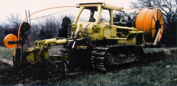
involved with what is referred to as “long haul” installation, which is the installation of fiber optic cable long distances
from city to city, for example a 250-mile project from Springfield, MO to Fort Smith, AR.
In order to help understand how a fiber optic route is installed, the steps of doing so will be talked about in the
approximate order in which things are done. It is important to understand that there is a stepwise procedure to
follow, however, some of these steps overlap and sometimes it is necessary to do things out of the order that is
mentioned here.
SP consultants, LLC as a multifaceted fiber optic cable route engineering company. In existence for 7 years, SP has
a great deal of experience in all of the aspects of fiber optic route installation. SP has been in the forefront of fiber
optic ring installation for some of the largest metropolitan areas in the continental United States. Examples include:
Houston, TX, San Antonio, TX, the Dallas – Fort Worth metro-plex, New Orleans, LA, Kansas City, MO, Tampa Bay,
FL, Seattle, WA, Portland, OR, Washington, DC, etc. In addition to fiber optic ring installations, SP has been
involved with what is referred to as “long haul” installation, which is the installation of fiber optic cable long distances
from city to city, for example a 250-mile project from Springfield, MO to Fort Smith, AR.
In order to help understand how a fiber optic route is installed, the steps of doing so will be talked about in the
approximate order in which things are done. It is important to understand that there is a stepwise procedure to
follow, however, some of these steps overlap and sometimes it is necessary to do things out of the order that is
mentioned here.
Preliminary Engineering
To properly engineer a fiber optic route project, an assessment is made of the needs and goals of the fiber optic
route. A map of the area is obtained in order to do a review of the possible route. Once the possible route is
selected, reconnaissance is performed to see if there are going to be some obvious problems that may make the
route completion impossible. Some areas are just too difficult to cross. Some examples include airports, railroad
crossings, and private property. Other things to consider are how difficult will it be to install the fiber in the exact
spot desired. Often, obstacles must be engineered around. Sometimes, the route can be built where desired but
cannot be achieved without great cost.
Once a desirable route has been selected, that looks like it will be achievable; a master plan is developed to
implement the activities of the route design. All along the route, research is done to determine the status of the
right-of-way (ROW). Surveying records are researched. Utilities such as gas, electric, water, sanitary sewer, and
storm sewer usually have drawings showing their locations and depths. Once everything that can impact the
location and depth of the fiber optic route is obtained, surveying can commence. Based on what is found according
to these records, a surveying plan is established.
Surveying
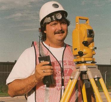
Professional Licensed Registered Engineer and Surveyor best carry out surveying of fiber optic routes. Before
beginning a survey, the nearest monuments and recorded benchmarks to the route, are located. Starting with a
monument that is convenient to where the survey is to begin, the survey team makes their way to the route
beginning. Often, there will be recorded benchmarks along the way. If there are no recorded benchmarks, they
will need to be created and recorded. The benchmarks are recorded in a logbook as well as the on board data
collector of the surveying instrument. Sketches are also made in the logbooks.
All along the route, the ROW’s and all of the above mentioned utilities are located as well as any previous fiber
optic carriers. The topography of the area including curb lines, buildings, fire hydrants, storm-grates, medians,
and any other pertinent objects are collected by the survey. The survey instruments are Nikon Total Station
DTM-500 series and GPS. They have onboard data collectors that are down loaded each night, backed up, and
e-mailed to the central office.
The data is collected in such a way that when the data is introduced into the electronic format, much of the
drawing is drawn already. This is accomplished through painstaking preparation and training on the part of the
instrument man in the field. We have found that this is the best way to get the field information into electronic
format quickly, correctly, and efficiently. The electronic format is the basis by which a complete accurate set of
drawings is produced.
Drafting
As was mentioned in the previous section, if the field data has been collected properly, many of the features are
already drawn when the data is introduced into the CAD software. This saves an immense amount of time. If
done correctly, the curb-lines, medians, manholes, valve boxes, storm grates, right-of-way lines, the fiber line,
and the survey control line are already connected. Driveways are already in place. Intersections are already
formed. Even the coordinates are correct if the drawing is done properly. This is extremely beneficial during the
permitting stage. If careful notes are taken in the field books, things such as business names, addresses, etc.,
can be inserted into the drawing for clarity.
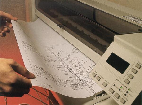
Once the whole route has been surveyed and inserted into an AutoCAD drawing, a survey control sheet and
route map are made. These two drawings are very important to permitting agencies. Without them, many
permitting agencies won’t permit the construction. After the survey control sheet and the route map are
satisfactorily completed, the construction drawings can be made. The construction drawings are made by cross-
referencing the route map into them. This is where the field notes such as addresses and business names are
inserted. This way, if there is a sweeping change that is to be done that will affect the whole route, it can be
done on the route map and all of the construction drawings will change with it. A re-plot is all that is necessary
to have updated drawings.
As was mentioned in the previous section, if the field data has been collected properly, many of the features are
already drawn when the data is introduced into the CAD software. This saves an immense amount of time. If
done correctly, the curb-lines, medians, manholes, valve boxes, storm grates, right-of-way lines, the fiber line,
and the survey control line are already connected. Driveways are already in place. Intersections are already
formed. Even the coordinates are correct if the drawing is done properly. This is extremely beneficial during the
permitting stage. If careful notes are taken in the field books, things such as business names, addresses, etc.,
can be inserted into the drawing for clarity.
Once the whole route has been surveyed and inserted into an AutoCAD drawing, a survey control sheet and
route map are made. These two drawings are very important to permitting agencies. Without them, many
permitting agencies won’t permit the construction. After the survey control sheet and the route map are
satisfactorily completed, the construction drawings can be made. The construction drawings are made by cross-
referencing the route map into them. This is where the field notes such as addresses and business names are
inserted. This way, if there is a sweeping change that is to be done that will affect the whole route, it can be
done on the route map and all of the construction drawings will change with it. A re-plot is all that is necessary
to have updated drawings.

Permitting
SP personnel are used to interacting with the most critical of permitting agencies. It can be amazing how many
permits are necessary to implement construction. Examples include: the County, State, Railways, Department of
Transportation, Corps of Engineers, and private entities for easement acquisition. Often, the different permitting
agencies desire the drawings to be in different scales, have different line types, and point out different things.
Commonly, the same set of drawings cannot be used for all the permitting agencies. Some agencies require
more detail. Some agencies only desire the route map. Some agencies look over every construction print in the
set and have standards that they are to follow. Some cities make the permit drawings a permanent record of the
utilities for the city. In addition, SP performs abstracting, private right of way easement acquisition, construction
damage settlement, computerized records, and a property owner line list.
| SP Consulting Fiber Optic Cable Route Engineering Company |